


 sales@itpstyli.com


9/29/26
Vector Group Calculations for Five Axis Probe Heads
A five-axis measurement routine requires your CMM to track more than the probe tip’s position in space. As the probe head changes angle, the system needs an accurate description of the stylus direction for each measurement position. Vector group calculations help software organize those directions when you work with five-axis probe heads, giving the system the orientation information it needs. Once you understand what those vectors represent, complex probe positions become easier to program and review.
Why Probe Direction Matters
When you position a probe for measurement, you need to know the direction the stylus will take as it approaches the surface. Cartesian coordinates describe position along the machine axes, while a vector describes direction. Your measurement software uses that directional information to interpret probe orientation and plan contact with the feature.
Five-axis measurement adds two rotary axes at the probe head to the CMM’s linear machine motion. As a result, changing the head angle changes the direction of the active stylus while the physical probe assembly remains the same. You need the stored probe orientation to match the position used during inspection.
Building Useful Vector Groups
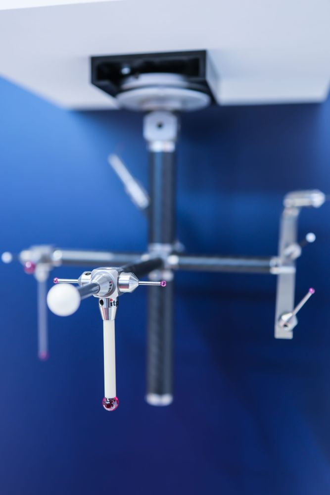
A vector group helps your inspection program organize probe directions for the required measurement positions. Exact terminology and handling depend on the CMM software you use, so you should follow your platform’s programming conventions. Still, the goal remains the same: connect the correct probe orientation with the intended measurement.
As you review a vector group, check the following details:
- That each vector points toward the intended measurement direction
- That the active stylus matches the correct probe-head orientation
- That the approach direction provides suitable feature access
- That surrounding geometry leaves enough clearance for movement
- That qualification data corresponds with the active configuration
Direction Needs Context
A vector alone doesn’t tell you everything about a measurement move. You also need to consider the probe’s starting position and the target surface’s location relative to that direction. Two points may share a similar approach vector but require very different head positions because nearby geometry affects access. Reviewing the vector within the part coordinate system gives you a clearer picture of the intended probe contact.
Connecting Angles With Vectors
When you program vector group calculations for five-axis probe heads, you’re connecting angular probe orientation with a direction the software can interpret within its coordinate system. Five-axis heads use two rotary axes, so movement along either axis may alter the stylus direction. Your software handles the mathematical transformation according to its own kinematic model, so you shouldn’t assume every platform represents those calculations the same way.
You also need to distinguish commanded head angles from the resulting stylus direction. Probe assemblies may include extensions or styli that alter the relationship between the head body and the contact element. Therefore, reliable programming depends on using the qualified active probe configuration.
Qualification Supports Orientation
Qualification establishes information about the stylus tip that the CMM needs for measurement. With articulating probe systems, your workflow must account for the orientations used during inspection based on the head and software configuration. Some systems require qualification at specific positions, while others support inferred or continuously managed orientations. Following the machine supplier’s procedure helps keep the stored probe information aligned with the measurement routine.
Checking Vector Group Logic
A calculation may look correct numerically while still producing a poor measurement move. You should review each programmed direction in relation to the feature because surface orientation affects the required probe approach. Simulation can also help you spot a vector that directs the stylus toward an obstruction or places the head in an impractical orientation.
During that review, pay attention to these points:
- Confirm that the vector faces the intended surface
- Check probe clearance throughout the entire approach
- Review head rotation near surrounding part geometry
- Confirm the selected stylus matches the programmed setup
- Recheck altered vectors after changing the probe configuration
Watch Coordinate Changes
Coordinate-system changes deserve extra attention when you reuse vector information. A vector defined in one part alignment may no longer describe the intended direction after you rotate or redefine the coordinate system. Your software may transform the information automatically, but you still need to verify the resulting approach during programming. A visual review can help you confirm the probe approach after you introduce a new alignment or reposition the part.
Choosing Styli For Access
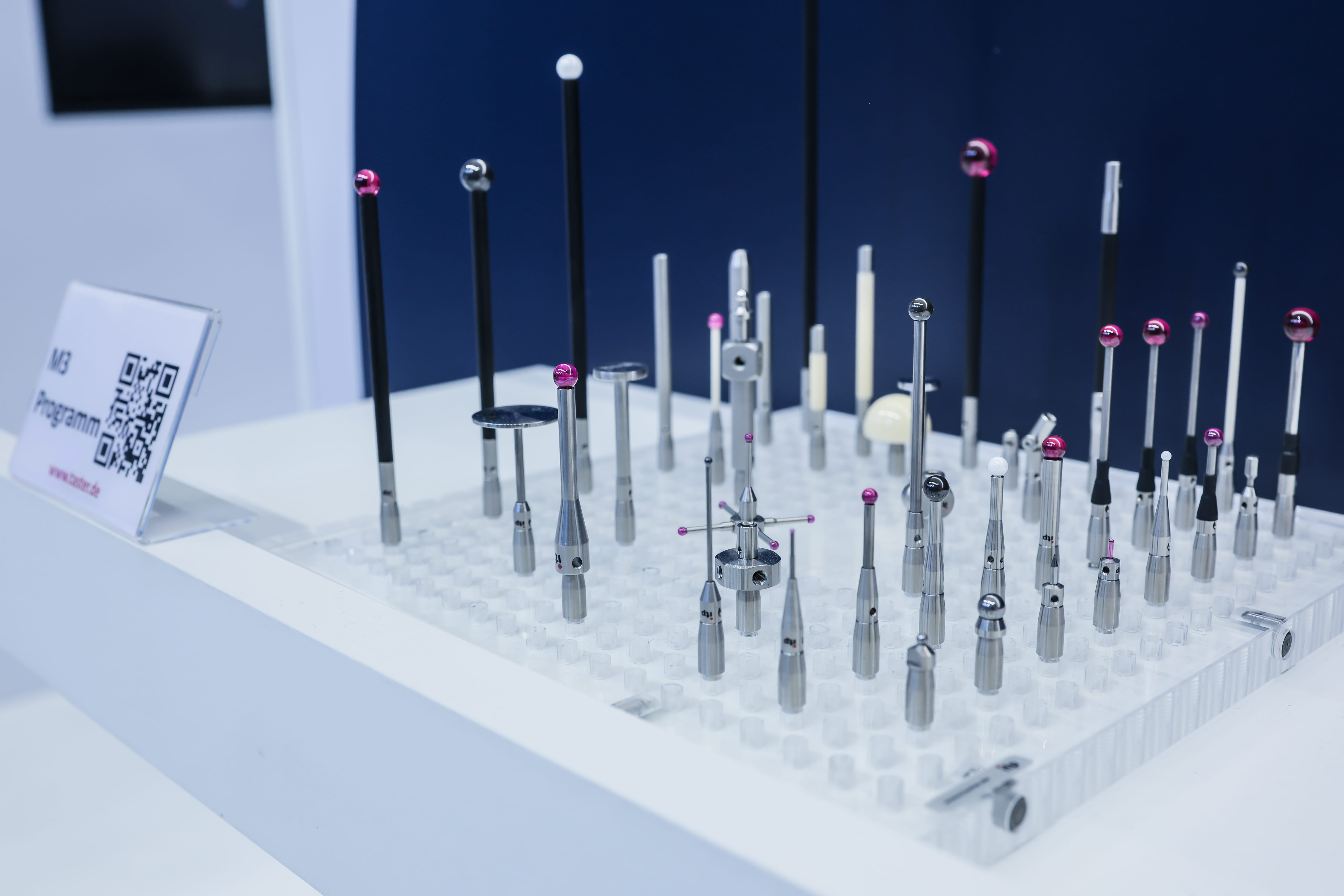
Your vector strategy also depends on the probing assembly attached to the head. CMM styli are the components that contact the workpiece and transfer that interaction through the probe system so the CMM can determine a measurement point. Stylus length and configuration affect which head orientations give you practical access to a feature.
A longer setup may help you reach a recessed surface, but its geometry still needs to suit the planned approach vector. You should consider clearance around the shaft as the head moves toward the target. Keeping the probe setup in mind helps you avoid a mathematically valid direction that creates an impractical measurement path.
Applying Calculations With Confidence
Vector calculations become easier to manage when you treat them as descriptions of real probe motion instead of isolated numerical values. Keep the active stylus configuration matched with its qualification data, then review each direction against the part geometry before running the routine. Five-axis systems give you considerable freedom to orient the probe, but each programmed direction still needs a clear measurement purpose.
You should also review the routine after altering the stylus assembly or introducing a new measurement angle. A configuration change may affect the probe information your program uses, so follow the applicable qualification procedure before relying on the revised setup. Once those relationships are clear, vector groups become easier to apply in complex five-axis inspection work.
When you understand the relationship between probe direction and head orientation, you can evaluate five-axis programming more confidently before the first measurement. Careful vector planning also helps you choose a stylus configuration that suits the geometry you need to reach. If your application calls for replacement styli or a configuration suited to a difficult feature, itpstyli offers options for a range of CMM measurement needs. Explore the available styli and accessories to find a setup that fits your next inspection routine.